Coordinate Mapping
Coordinate Mapping turns a position in the camera picture (pixels) into a position on the machine (millimetres), so a PLC or a robot can use it directly. It needs the Machine Coordinate Transformation licence.
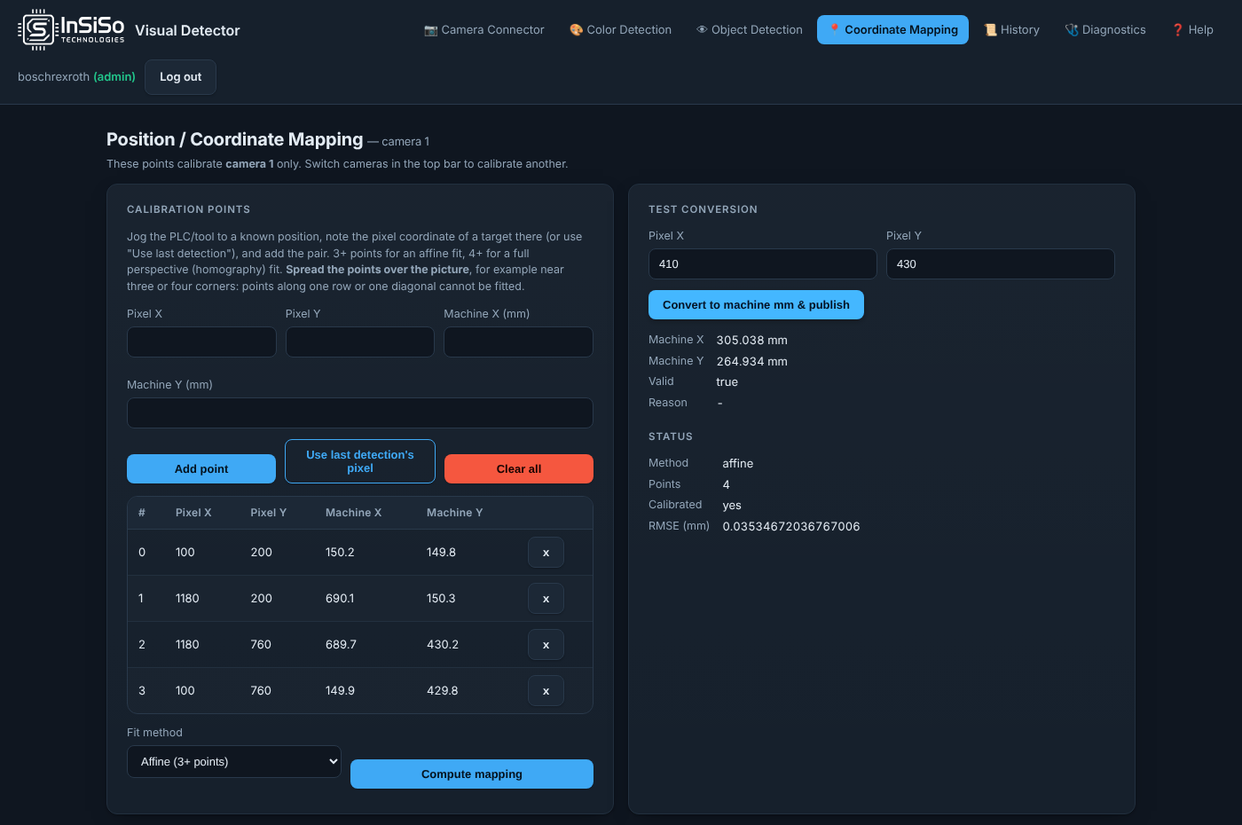
Calibrate
Each camera is calibrated on its own. The page title names the camera; switch cameras in the top bar.
- Put a target where the camera sees it and jog the PLC or tool to it. Note the machine position.
- Enter the target's Pixel X and Pixel Y, or press Use last detection's pixel to take the centre of the last object found.
- Enter Machine X (mm) and Machine Y (mm), and press Add point.
- Repeat at three or four places spread over the picture, for example near the corners. Points along one row or one diagonal cannot be fitted.
- Choose the Fit method: Affine (3+ points), or Homography / perspective (4+ points) when the camera looks at the belt at an angle. Press Compute mapping.
Status shows the method, the number of points, whether the camera is calibrated, and the fit's error (RMSE (mm)). Clear all removes the points.
Check it
Under Test conversion, enter a pixel position and press Convert to machine mm & publish. The page shows the machine position and whether it is valid.
What it publishes
Once calibrated, every object from Object Detection is also published in machine millimetres under coordinates/ on the Data Layer: x-mm, y-mm and position-valid. Element i of coordinates/ is element i of object/. Colour blobs stay in pixels.